Design & Build A Custom Thermal Vacuum Shroud
I've been head down lately putting together all the various parts for this stratlab build, and today's post is focused on building out the ability to monitor and control what happens inside the vacuum chamber.
For those of you new to this, my working hypothesis is that physics hasn't changed but equipment has, and older industrial quality equipment is on the market that isn't quite as fancy as cutting edge modern stuff but still does the job very well.
The goal is to get 80% of the performance of NASA-grade research at 10% of the cost, delivering either test services to clients or for internal use working on the MetSonde.
Thermal Vacuum Chamber Performance Goals
Now, my requirements for the MetSonde project are to simulate conditions between 30,000 and 60,000 feet and temperatures down to -60 °C, but I do want the ability to simulate much higher altitude and lower temperatures just in case anyone comes along asking for help testing their CubeSat idea.
To be clear, my current setup (chamber and Edwards RV3 pump) will not meet the CubeSat Thermal-Vacuum Cycling Test Specification for vacuum, which is on the order of 1e-5 Torr, but it will provide a much better opportunity to test conditions than either ignoring the test completely or just chunking your CubeSat in a bed of dry ice and figuring that is close enough.
The Shroud
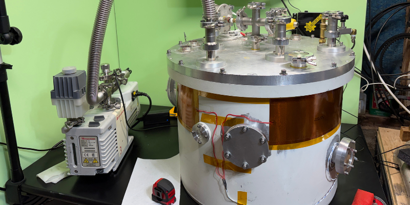
My chamber is about 85 L (20.5" ID, 15.5" high), see Appendix 1, and my plan is to cool with liquid nitrogen (LN2) running through 1/4" stainless steel tubing into and out of the chamber through the single KF40 port on the lid. I'm using the LDS NW40xSWG25DT for this.
I could try to cool the whole chamber, which for some balloon coupon testing might be useful just to give the balloon room to expand, but it also seems wasteful if I want to test a small device like the MetSonde board, which in general terms is a ~3" x 2" (75 mm x 50 mm) PCB, or a 1U CubeSat (10 cm x 10 cm x 11.35 cm).
I decided to build a custom shroud for this, which is basically an insulated pocket inside the vacuum where we focus our cooling efforts in order to A) have more control over temp and B) be efficient with the LN2.
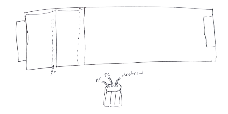
It'll be an eight walled simple structure, each wall about 5" wide and 12" high, folded into an octagonal shape. Here's the general idea:
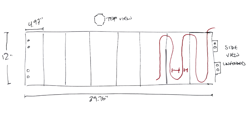
I'm building it out of .083" aluminum because I happened to have a 4' x 8' sheet of it on hand and aluminum is easy to work with and conducts heat well.
At broad strokes, the SS tubing enters the chamber, attaches to the shroud in a serpentine pattern along each wall, then exits the chamber.
Shroud Treatment
The shroud has heating pads on it to trim temp up, and I'll construct an MLI (Multi Layer Insulation) blanket to wrap the shroud in using mylar and tulle netting for alternating layers, sewn onto a nomex fabric so it's relatively easy to handle and slide on and off.
I'll sew in overlapping pockets to drop aerogel into, but the aerogel won't be in the v1.
I'll dive into the heating pads below, and write more on the MLI blanket in a future post.
Heating & Cooling
Conceptually, heating and cooling is simple. You run more LN2 through the tubing faster to cool things down, turn on the heaters if you overshoot, and if you get the flow right you're sorted. Sounds straightforward, right? Ho ho ho...
Monitor & Control
We'll start by breaking the problem into two pieces:
- Cooling and heating of the chamber
- Monitoring internal chamber conditions
Shroud Cooling
The cooling aspect is regulated by how much LN2 flows through the stainless tubing, and how quickly. I bought a 50L Cryofab Stainless Steel Dewar (CFL-50-SS) off eBay which has a method to build internal pressure in order to generate enough pressure to push out the liquid LN2 through the insulated vacuum hose.
I don't see a way to control the flow easily with that, so I picked up both a Whitey SS-31RS4 1/4" Needle Valve and an ASCO 8262H114LT Solenoid in order to modulate flow at the end of the vacuum insulated hose.
That should give me the ability to control the flow rate with the needle valve and then automate the on/off with the solenoid.
How it should work is the LN2 will get pushed out of the dewar by the pressure of the boil-off, flow through the tubing and cool the chamber, then escape to atmosphere at the far end.
This gets the tubing (and anything attached to it) very cold; LN2 has a boiling point of -196°C.
That sounds awesomely cold (though not quite near space, which can get to -250°F) but we still have a few issues to manage.
First, I only need to get to -70°C for MetSonde testing. Second, I need a way to monitor the temperature of both the shroud and the internal ambient shroud environment. Third, if I overshoot, I need a way to heat the shroud back up.
We'll start with the heating part first.
Shroud Heating
The standard way to do this if you're NASA is to spend about $700 per flexible heating pad to get exactly what you want. I'd rather not drop a few thousand bucks on heating, so I got on eBay and picked up 7 MINCO HK10003C heating elements plus a PTSHeat 31470W pad and a LRS-600-24 600W 24V 25A power supply for $400 total.
I'll have the LRS-600-24 provide the power and manage it with a Watlow F4SH-KKAO-01AC.
Heating the shroud is mostly important (as far as I understand it) in terms of trimming back up if I overshoot with the LN2 and go too low.
I'll bond the flexible heating pads to the aluminum with Masterbond (their rep recommended EP21TCHT-1) and use a hard silicone roller to make sure I get rid of any bubbles between the heating pad and the aluminum.
Shroud Condition Monitoring
Still, it's not like I can just eyeball the temps during a run. I mean, I can't even see it (we don't have a viewport yet on the chamber, and even if we did, the shroud will be wrapped in insulation). I can't just reach out and feel the shroud either; it's inside the chamber, plus I'd freezer-burn my hand off even with the heaters at full blast.
The answer, of course, is sensors.
When it comes to sensing temp, we have two main options: Thermocouples and RTD. Each has strengths and weaknesses.
After getting advice from a couple of enormously generous folks at the National Center for Atmospheric Research (all faults and misinterpretations are mine), I decided to use both. Here's what they suggested:
For this temperature range, I would tend to use RTDs — negates the Seebeck voltage issues altogether. The RTD should measure well as low as 175 K or so (60 kft is 212 K per US standard atmosphere). If however he wants to measure 77 K on the shroud, then a cryodiode or a type T is really the best way to go.
For those of you who need a quick refresher on K, which is no one in aerospace but probably most of the rest of us, it stands for Kelvin, which is what the physical sciences use to talk about temp instead of C or F.
0 Kelvin isn't just frozen, it's the absence of all thermal motion. Water freezes at 273.15 K. Liquid nitrogen is 77 K. You can't get colder than 0 K.
To convert Kelvin to Celsius, you subtract 273.15 from the Kelvin value:
Formula:
Calculation:
So, when they say "as low as 175 K," they are referring to temperatures around -98 °C (-145 °F).
Whew, the learning tap is wide open for me at this point!
Thermocouples for Thermal Vacuum Chambers
Thermocouples come in various types (T, K, J, etc). For a cryo-TVAC, the best option I identified is a type T thermocouple. I bought 5 of the Omega 5TC-TT-T-36-36, then realized I had another problem.
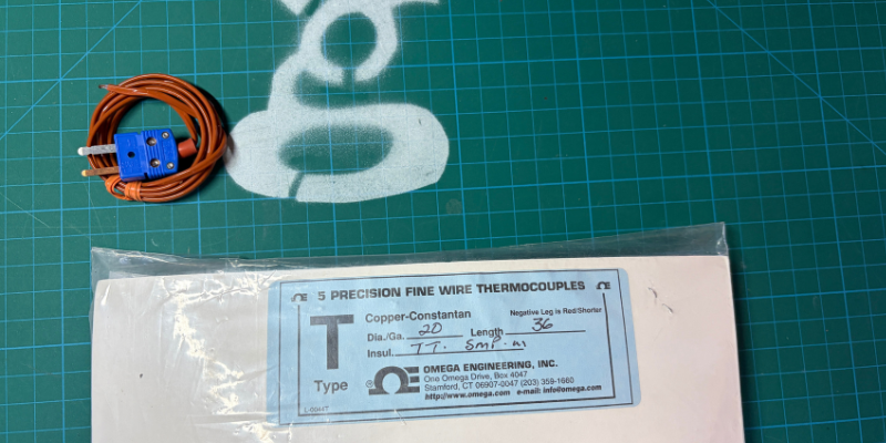
Thermocouples work by generating a difference in voltage (the "Seebeck effect" mentioned above) between two wires that are two different metals (Copper-Constantan). You can't just solder the wires to pins and figure that the data will pass through; the new thermoelectric junction generates a new Seebeck voltage, distorting your reading further.
You also have to account for the fact that there's a pretty radical temperature transition between the inside of the vacuum and the outside.
To account for this, I decided to buy special thermocouple feedthroughs and use a couple of the KF25 ports scattered about the lid to be dedicated thermocouple ports.
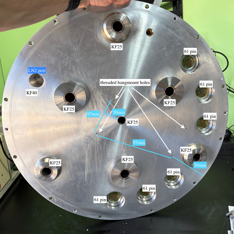
I hunted around the internet to see if I could find a KF25 feedthrough for multiple thermocouples, and the good folks at MPF Products quoted me about $240 ea for dual feedthroughs (4 total attachments per KF25 for 2 thermocouples per port). I ordered 3 so I'd have a total of 6 potential thermocouple options.
This means I'll be able to measure the following points inside the chamber:
- 2 faces of the shroud
- the DUT
- the inside wall of the chamber
That's 4 measurement points, and I spent an extra $240 so I could have 6. Why? A long time ago I learned the old Two is one and one is none phrase, so I figured options for 2 extra thermocouples wouldn't hurt. If you read this and think, "My God Nik, why aren't you using a thermocouple on [xyz]", well, I can. Just let me know
RTD for Thermal Vacuum Chambers
As noted above, RTDs ("Resistance Temperature Detectors") work well down to 175 K, so they're great for checking ambient temperatures in vacuum when I'm testing for high-altitude balloons. For CubeSat work they're not as useful, but the majority of my focus is on balloon work.
The downside is that they're not particularly cheap; one cryogenic-rated RTD can run about $40. I get it, thermocouples are cheaper but need expensive ports.
The massive upside is I can use the 61-pin connectors liberally scattered about the lid (6 of 'em!), so getting the data out is substantially easier and cheaper than paying $120 per thermocouple.
I ended up ordering both, and plan on using the RTDs for ambient inside the shroud and then inside the greater chamber, and type T thermocouples for all the surfaces.
Is That A Wrap?
As all of these come in I'll put it all together. As with all these projects, I'll make inevitable accidental mistakes.
If you're an aerospace thermal vacuum chamber wizard and read this... after you're down spitting out your coffee at the temerity of a C+ high school student putting together a TVAC in their garage, I'd love to hear how I can avoid some of the worst errors here.
Let me know what mistakes I'm making via the contact page. If you're in San Diego and want to see this thing, ping me and I'll give ya the tour!
Thanks so much for reading, and if you have something you want to test that'll go up higher than Uncle Rico can throw a football, hit me up.
Appendix 1 - GK TVAC Chamber Specs
Gristle King Thermal Vacuum Chamber (GK TVAC)
Chamber: 50.2 lbs Lid: 55.8 lbs
Lid (1" thick Al)
Lid Ports
- 7 x KF25
- 6 capped off
- one has a 4-way tee:
- in lid
- capped
- Wallace & Tiernan absolute pressure gauge reading mm mercury from 1-100, with a "not calibrated" sticker on it
- yellow knob with a 4-pin connector, labeled Varian ConvecTorr vacuum gauge, call 1-800-8-VARIAN"
- 1 x KF40
- 6 x 61 pin bayonet SEALTRON M83723/81H2461N 9623
- unknown pipe tapped in. Has a valve on it: Robbins Aviation Inc. INSG103-2P. VAC 3500 PSI. PAT 2994344. CAN 634960z. Looks like 1/4" NPT fittings.
Monitoring
- see 4-way tee above for absolute pressure gauge and convectron gauge
- 1 thermocouple taped on with metallic tape
The lid has 4 blind threaded holes for #6-32 screws, each hole approx 12 mm deep. They form a rectangle that is offset from center. The rectangle is 97 mm x 215 mm, sits 4 ⅝" in from the edge of the lid, and extends 3 cm past the center KF25 port.
Chamber (20.75" ID, ~15.5" high, approx 85 L)
1/8" thick aluminum Circular chamber with 12 securing bolts that screw in through the lid.
Chamber Ports
Port 1
- 8 1/16" OD port cover
- 8-bolt, ~29 cm CTC
- 6 1/8" ID port
- O-ring, black, and 3.1 mm thick
- O-ring groove ID 6 5/16"
- O-ring groove radial width: 4.5 mm
Port 2
- 4.5" / 115 mm OD port cover
- 102 mm CTC bolt pattern, 6 bolts
- outer flange diameter: 114.41 mm
- 62 mm ID port
- brown O-ring, 3.5 mm thick
- O-ring ID ~ 2 5/8"
- O-ring groove radial width: 4 mm
Port 3
- 4" OD 2-piece plate
- 9.78 mm thick; inner circle is a 3" plate, 6.41 mm thick; held in by a flange 59.64 mm wide
- 5/32" Allen-key bolts
- 6-bolt pattern
- ~88 mm CTC bolt pattern
- threaded port, ~50.29 mm ID, 37 mm deep
- bronze/brown O-ring, ~2.44 mm thick
- O-ring ID: 2.5"
- O-ring groove radial width: 3 mm
Port 4
- 2.25" diameter plate
- threaded for 4 bolts, 48 mm CTC, 9/16" Allen-key heads
- 2-piece port: outer ring is 2.25", inner port is 1" diameter, inner/insert plate is 1.5" diameter and 1/4" thick
- O-ring, 1.62 mm thick
- O-ring ID ~28.78 mm
- O-ring groove radial width: 2.13 mm
- ID: ~25.26 mm
External Chamber Heating
- 4 copper colored pads, ea 12" x 5", labeled "MINCO 0103 HK5516R20.4L12E", wired in parallel. 20.4 Ω per pad, and 20.4/4 ≈ 5.1 Ω total.